|
GENERAL INFO + LIMITATIONS |
 |
The software
performs Analysis, Design, Estimation & Costing of Structural Steel Floors
and Columns. Floor Plan shall be at a given
Uniform Level
(2D). Multiple Level Floors (3D) cannot be analyzed.
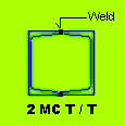
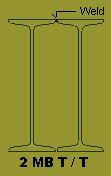
All Columns shall be 2MC T/T or 2MB T/T Box.
The Software
basically requires a User to enter floor data for Joints, Columns, Beams,
Slabs (Grating or Chequered Floor) , Point loads & Continuity. The rest of the things are taken care of by the
software.
The results are displayed in the form of BM & SF, Beam Design Details,
Quantities, Cost & Column Loads.
Graphics option are available for display and tabular Format is available for
Editing and Deleting Data.
A User should Delete / Edit Input-Data through the
various Program Options only. If any editing is done
outside the design environment than Data files may become corrupted.
Extensive Printing options are available under each
display.
Printing is straight forward with default set of values ( Arial Font, 8 mm
Thick, Bold, Portrait ).
The best way to go about the software is to Mark on the Floor Plan, Joint, Beam,
Column and Slab Numbers. A Joint represents a Column location or an intersection
between 2 Beams. The Beams are represented by its location in the form of Right
Hand Side (RHS) & Left Hand Side (LHS) Joint numbers. The Slabs are represented
by LEFT BOTTOM & RIGHT TOP joint numbers. All Joints will have X & Y
Co-Ordinates, Top Left corner is taken as origin (0, 0). Joint / Beam / Column /
Slab numbers should start with " 1 " and should not be repeated.
The Program will generate automatic Joint, Beam, Column & Slab Numbers from the
information given in Project File. Some of these Numbers / Members may not be
required & shall be deleted in a systematic manner as explained in the following
chapters. The Final Plan Graphics should look exactly as the Floor Plan. |
 |
Cantilever beams
cannot be analyzed.
Only Vertical Loads & End Moments on Beams are Envisaged.
Lateral & Compressive Loads on Beams are not Permitted.
|
 |
Beams / Columns /
Slabs shall be along two mutually perpendicular axis (X and Y). Polygonal
(Multi-sided) Floors cannot be analyzed. |
 |
Only three (3) Load
Cases can be analyzed per File, viz :
● DL + LL
● { DL + LL + Wind Or Seismic End Moment (WL1). } * 0.75
Wind Or Seismic End Moment shall be entered by the user on individual beams
having Columns supports.
● { DL + LL + Wind Or Seismic End Moment (WL2). } * 0.75
Whatever will the value of WL1, the program will reverse its sign (Multiply it
by
- 1) and use it as the default 3rd Case.
● Multiplication Factor of 0.75 will be applied within the Program by
default.
End Moments (Wind or Seismic) are obtained by running 2-D or 3-D Portal Frame
Analysis programs separately. User may use our 2-D
Frame Analysis software for calculation of End Moments.
More cases can be obtained by manipulating initial values as given in the
project file or individual Beam and Slab files. For example Analysis option can
be re-run with LL decreased by 0.8 (0.5* 0.8 = 0.4 T/M2). Similarly masonry
thickness can be decreased to get
desired loading on the floor.
However a designer has to 1st copy the original file in to another file (using
Copy Option) & do the above mentioned modifications.
|
 |
Export to Excel :
When the " Analysis Result -> Bending Moment & Reaction " option is Run, a Text
file is automatically created. This File will open in Any Text Editor. You can
also Open this Text File in EXCEL.
Start Excel -> File -> Open -> Delimited ->Next : Delimiters -> Comma ->Next ->
Finish.
Now you will notice that Complete Data is displayed in Excel Spread Sheet.
If more than One File is Created, Corresponding to Each of Load Cases, than Open
Excel Sheet for Each File (Load Case). In Excel Sheet Editing, Deleting,
Sorting, Printing & Merging of Data/Files/Excel Sheets is Extremely Easy. This
way any no. of Load Cases can be Manipulated.
Similar Text files are created in " Shear Corrected BM & SF " (Design BM & SF) &
" Column Loads " option for Exporting
Results to Excel Spread Sheet & its subsequent Manipulation.
|
 |
Intersecting Joints
between two Beams (Main & Secondary) is assumed as Hinged. Hence no Moment
transfer is envisaged. |
 |
Connection between
End Column and Beam is considered as Hinged. Hence no Moment transfer is
envisaged between Column and Beam. However End Moments can be applied at joints
as mentioned above under Load Case WL1. |
 |
For Std. Design of
Chequered Plate & Grating, refer SUPER CIVIL CD
SOFTWARE. |
 |
For End Connection Details
Refer Standard Drawings. |
 |
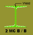
Five Types of Beam
are Possible.
(a) MC
(b) MB
(c) MC welded Toe to Toe (T / T)
(d) MC welded Back to Back (B / B)
(f) MB welded Toe to Toe (T / T) |
|


 |
 |
Only Two Types of
Columns
are Possible.
(a) MC welded Toe to Toe (T / T)
(b) MB welded Toe to Toe (T / T) |
|

 |
 |
Following Sections
are Possible for Beams & Columns.
(a) ISMC Section:
ISMC 100, 125, 150, 200, 250, 300, 350 & 400.
(B) ISMB Section:
ISMB 100, 150, 200, 250, 300, 350, 400, 450, 500, 550 & 600.
|
 |
Minimum Computer RAM memory
of 1 GB is recommended. |
 |
Use Laser OR Ink
Jet Printer.
|


|