| Hidden
Beam marking in flat slab is different than the normal floor plan GA.
1: Mark the Hidden
Beams (Column Strips)
in the same way as you Mark the
Normal Beams but remember the following differences.
2: Hidden Beam (Column
Strip) depth shall
= Flat Slab (Middle
Strip) Thickness.
3: All Flat Slab (Middle
Strips) thickness
shall be uniform.
4: Initial (Trial) Flat
Slab Thickness =
Max.
Span of Beam or Slab in the Floor in MM ÷ 28.
5: Keep Column Size as
Large as Possible, Larger the Column size lesser
the Flat Slab thickness.
6: Minimum Column size
allowed is 300 x 300 MM.
7: Try to Avoid
secondary beams, i.e. hidden beams resting on one another.
8: Avoid concentrated
loads, else flat slab thickness will be very high.
9: Convert wall line load
in to UDL as w ÷ (0.6 * slab_span). and avoid beam
below wall line load. Refer IS 456-2000, clause
24.3.2.
10: Hence convert all
internal partitions in to equivalent UDL & avoid beams.
11: Try to Keep Minimum
spacing of beams at 2.0 M C/C.
12: In order to get most
optimum design keep the slab and beam spans
uniformly within 20 % of each other.
13: Spacing of columns
shall be as uniform as possible within say 20 % of each
other.
14: Avoid Eccentricity of
Walls vis a vis Hidden Beams and Columns.
15: One Way Shears are
calculated at effective depth from Column face and
Punching shear at deff ÷ 2.
16: BMs
are calculated at Column face.
BM
& SF are calculated at Beam Center Line for Beam to Beam Joint.
17: Flat Slab depth to be
revised, if steel area exceeds 182 cm2.
18: In Case of Un-safe
Hidden Beam design Reframe the Plan or Revise Slab
Depth or Column Size or Concrete Grade.
19: Flat Slab Design is
meant for Vertical Loads only, for Lateral Loads
Shear walls
or Bracing
Systems shall be Provided.
20: For Analysis &
Design of Shear Wall refer our Super
Civil CD software.
21: For Design of Bracing Systems refer our Steel_2007
software.
22: Designer to Calculate DL + LL Moments in
Columns from both the Axis. The
Width and Depth of Hidden Beam will be
displayed after running Design
option. Frame Analysis under DL +
LL shall be performed along both the axis
and Column Moments shall be entered using
Column Display Option.
If DL + LL Column Moments are not Entered
then Design of Flat Slab
will be in-correct.
23:
Use any 2/3 D Frame Analysis Software or for Quick Results Use Our Own
2
D Frame Analysis Software
to Perform Frame Analysis in Each Direction.
24:
Beam Loads can be taken as tributary or UDL for Frame Analysis.
25: Main Steel is to be
placed in Longer Direction & not in Shorter Direction.
26: Convert Non
Rectangular Column into Equivalent Square Column
before Designing.
27: Min Reinforcement % in
Either Direction = 0.20 %.
28: Reinforcement Spacing
Shall not Exceed 2 x Depth.
29: Sometimes Design gives Congested steel or Links, Use Substitute
Program
given with software to change Re-bars numbers, Spacing
and Link diameter.
30: Use High Grade of
Concrete Preferably M 30 or M 35.
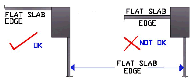
31: At Ends and Corners
the Flat Slab shall Extend up to or beyond Outer Edge of
Column Else Flat Slab will Fail in
Punching. Refer Details as under.

32: Large openings cannot
be provided in Flat Slab.
33: Small openings say
<= 300 MM can be located near the center of Slab.
34: Staircase panel shall
be treated as normal slab & not as opening,
Program will calculate the Loads
automatically.
35: All Walls are
assumed as Brick wall of 1.8 T/M3 density, if wall is of different
density then width shall be changed proportionately.
36. In case of Unsafe Flat Slab / Hidden beam Design, any one or all of
the
following measure shall be adopted.
 Reframe General Arrangement (GA) / {Beam layout} Plan.
 Revise Hidden Beam /
Flat Slab Depth.
 Increase Column
Size.
 Increase Concrete
Grade.
37.
When the DL + LL Column Moments are high compare to DL + LL vertical
Loads, the program will indicate Higher
column size at upper floors & not at
lower floors. A designer has to overcome
this problem by adjusting the
column size or % of reinforcements along
the column floors.
|