|
INTRO, LIMITATIONS & SPECS |
|
|
 |
Composite Floor
Design is as per Euro 4 & IS 800 : 2007.
Box Column is not composite & is designed as per IS 800 : 2007.
Composite floor using profiled sheet decking consists of steel beams, steel deck, shear connectors, steel mesh and cast in-situ concrete in such a manner that they would act monolithically.
Composite floor comprises profiled steel decking as the permanent formwork to the underside of concrete floor spanning between support beams. The decking acts compositely with the concrete
slab. It also supports the loads applied to it before the concrete has gained adequate
strength (during construction stage). A steel mesh is placed in the concrete floor to avoid effect of cracks and shrinkage. |
 |
Read all
Beam to Beam, Beam to Column Shear Connection design with reference to standard
details given in the software. |
 |
The software
performs Analysis, Design, Estimation & Costing of Composite Steel Floors
and Columns. Floor Plan shall be at a given
Uniform Level
(2D). Multiple Level Floors (3D) cannot be analyzed.
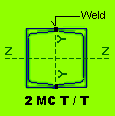
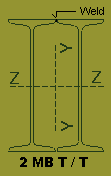
All Steel Columns shall be Box type i.e. 2MC Toe to Toe OR 2 MB Toe to Toe
Welded without any Gap.
The Software
basically requires a User to enter floor data for Joints, Columns, Beams,
Concrete Slab + Deck profile & Point load. All beams are Simple Supported. The rest of the things are taken care of by the
software.
The results are displayed in the form of BM & SF, Beam Design Details,
Quantities, Cost & Column Loads.
Graphics option are available for display and tabular Format is available for
Editing and Deleting Data.
A User should Delete / Edit Input-Data through the
various Program Options only. If any editing is done
outside the design environment than Data files may become corrupted. All
Data should be Strictly
"Entered" as explained in following steps.
Extensive Printing options are available under each
display.
Printing is straight forward with default set of values ( Arial Font, 8 mm
Thick, Bold, Portrait ).
The best way to go about the software is to Mark on the Floor Plan, Joint, Beam,
Column and Slab Numbers. A Joint represents a Column location or an intersection
between 2 Beams. The Beams are represented by its location in the form of Right
Hand Side (RHS) & Left Hand Side (LHS) Joint numbers. The Slabs are represented
by LEFT BOTTOM & RIGHT TOP joint numbers. All Joints will have X & Y
Co-Ordinates, Top Left corner is taken as origin (0, 0). Joint / Beam / Column /
Slab numbers should start with " 1 " and should not be repeated.
The Program will generate automatic Joint, Beam, Column & Slab Numbers from the
information given in Project File. Some of these Numbers / Members may not be
required & shall be deleted in a systematic manner as explained in the following
chapters. The Final Plan Graphics should look exactly as the Floor Plan. |
 |
Cantilever beams
cannot be analyzed.
Only Vertical Loads & Axial loads on Beams are Envisaged.
Lateral Loads & End BMs are on Beams are not Permitted.
|
 |
Beams / Columns /
Slabs shall be along two mutually perpendicular axis
(Z and Y). Polygonal
(Multi-sided) Floors cannot be analyzed. |
 |
Only Dead + Live Load
Case is analyzed by the software.
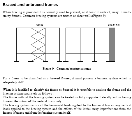
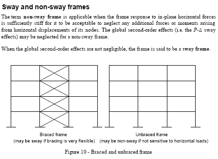
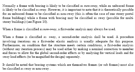
It is assumed that structure is braced and lateral forces are resisted by only
Braced Frame. A Frame which is braced as well as non sway will be
preferred for composite construction. Non Braced elements are designed only
for DL + LL.
Refer the following Euro 4 Code (EC4) explanation.
|
 |
Intersecting Joints
between two Beams (Main & Secondary) is assumed as Hinged. Hence no Moment
transfer is envisaged. |
 |
Connection between
End Column and Beam is considered as Hinged. Hence no Moment transfer is
envisaged between Column and Beam. |
 |
After data input, the user has
to switch over to graphic option for visual checking of joints / columns / beams
/ slab nos. When the data is error free the user can run the Analysis,
Design and Quantity options. The various results are also available through
display or print options. |
 |
Analysis, Design and Quantity
options should be run in strict order, else program will give unexpected
results. |
 |
Program creates
automatic Joint numbers as per nos. of Horizontal & Vertical Grids. Here Grids
means Beams coming along Column center lines as well as all Internal
Beams not aligned with columns. A user has to input Information regarding
Horizontal & Vertical Grids while creating Project File. |
 |
A user can delete
the Joints not required by using Joint Option. |
 |
Joints will be
automatically re-numbered when "UPDATE" button is clicked or at "EXIT". |
 |
Remember to Delete / Edit Corresponding Beam /
Column / Slab Member, whose Joint has been deleted. |
 |
Always delete Beam
/ Column / Slab member from the "END" to facilitate further Editing. After
Deleting press "UPDATE" button for re-numbering of members. |
 |
After Deleting
corresponding Beam / Column / Slab Member & Updating, edit the required Joint
Numbers of affected Beam / Column / Slab Members. |
 |
Go through the "READ
ME" Button for better understanding of that particular Option. |
 |
Only 2 Types of Beam
are Possible.
(a) MC
(b) MB |
 |
Only Two Types of
Columns
are Possible.
(a) MC welded Toe to Toe (T / T)
(b) MB welded Toe to Toe (T / T) |
|
 |
 |
Following Sections
are Possible for Beams & Columns.
(a) ISMC Section:
ISMC 100, 125, 150, 200, 250, 300, 350 & 400.
(B) ISMB Section:
ISMB 100, 150, 200, 250, 300, 350, 400, 450, 500, 550 & 600.
|
 |
 |
 |
 |
 |
End Reactions are obtained by running 2-D or 3-D Portal Frame
Analysis programs separately. User may use our 2-D
Frame Analysis software for calculation of End Reactions of Braced
Frames.
|
|
|
|
IMPORTANT INFO / SPECS
|
|
|
 |
1. Designer to
Select Deck Profile as per Allowable total Loading Intensity
corresponding to Maximum span of Deck, from the Load
Table provided by
Deck Manufacturer. The Deck deflection shall
not exceed Span / 180 or 20 MM
whichever is less. The Minimum Yield stress of DECK
shall not be less than that
of Structural Steel.
2. The Composite floor
design is based on the assumption that all beams are
simply supported. There is no Hogging bending moment due to
DL + LL or Wind
or Seismic.
3. The Complete System
shall be Braced with Shear Wall or with Crossed Braced
Frames, resisting all lateral Forces.
4. It is Preferred to
Design all Braced Frames as Non-Sway Frames,
refer IS 800 : 2007.
5. Select the Deck Span
requiring no Props.
6. Restrict thickness of
Galvanized Deck profile to 1.25 - 1.50 MM.
7. Diameter of
automatically welded Studs are restricted to 19 MM.
8. Depth of Deck
Profile > 85 & < 35 MM not Permitted.
9. Decking Sheets shall be
attached to each other & to all permanent supports
using screws or shot fired nails.
10. Thickness of Concrete
above Rib < 55 MM not Permitted.
Fire Rating of 2 Hours.
11. Deck Width (br) <
50 MM not Permitted.
12. Minimum Clear Cover to
Stud from Concrete Top = 20 MM.
13. Deck Sheeting
Longitudinal over lap
= 150 ~ 300 MM & Min.
Side Over lap = 30 MM as per Manufacturer's Specs.
14. Min. Bearing of Deck
Profile on Steel = 50 MM.
15. Aggregate Size not
> than 0.4 * Conc. thickness above Rib.
16. Attach minimum of one
Stud to every decking trough.
17. However 2 Studs can be
attached if required by design.
18. Stud Transverse
Spacing not > 4 Ø.
19. Stud Longitudinal
Spacing > 5 Ø.
20. If Frequency of Vibration of Beams < 4 Cycles/Sec,
Designer to change
Section.
21. Height of Stud > 4 * Ø of Stud for Ductile classification.
22. Head Ø of Stud = 1.5 * Ø of Stud.
23. Minimum Yield Strength Fy for Deck Profile Shall be 250 N/MM2
24. Clear Cover to Stud from Top shall be 20 MM.
25. Clear Cover to Mesh Reinforcement from Top shall be 30 MM.
|
 |
Export to Excel :
When the " Analysis Result -> Bending Moment & Reaction " option is Run, a Text
file is automatically created. This File will open in Any Text Editor. You can
also Open this Text File in EXCEL.
Start Excel -> File -> Open -> Delimited ->Next : Delimiters -> Comma ->Next ->
Finish.
Now you will notice that Complete Data is displayed in Excel Spread Sheet.
If more than One File is Created, Corresponding to Each of Load Cases, than Open
Excel Sheet for Each File (Load Case). In Excel Sheet Editing, Deleting,
Sorting, Printing & Merging of Data/Files/Excel Sheets is Extremely Easy. This
way any no. of Load Cases can be Manipulated.
Similar Text files are created in " Shear Corrected BM & SF " (Design BM & SF) &
" Column Loads " option for Exporting
Results to Excel Spread Sheet & its subsequent Manipulation.
|
 |
Minimum Computer RAM memory
of 2 GB is recommended. |
 |
Use Laser OR Ink
Jet Printer.
|


|