|
DESIGN OF CANTILEVER TYPE WATER TANK CLOSE OR OPEN FROM TOP |
|
|
|
|
|
DESIGN RESULT |
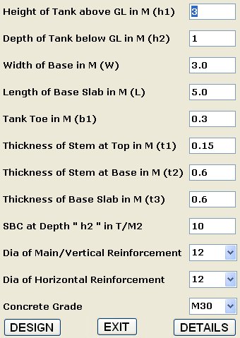
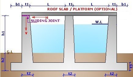
| DESIGN OF CANTILEVER TYPE WATER TANK RESTING ON GROUND - TYPE II Height of Tank above GL in M (h1): 3 Depth of Tank below GL in M (h2): 1 Width of Base in M (W): 3.0 Length of Base Slab in M (L): 5.0 Tank Toe in M (b1): 0.3 Thickness of Stem at Top in M (t1): 0.15 Thickness of Stem at Base in M (t2): 0.6 Thickness of Base Slab in M (t3): 0.6 Vertical Load From Roof Slab in T/M (V): 0 Horizontal Load From Roof Slab in T/M (H): 0 SBC at Depth " h2 " in T/M2: 10 Dia of Main/Vertical Reinforcement: 12 Dia of Horizontal Reinforcement: 12 Concrete Grade: M30 Steel Strength (fy) [N/MM2]: 415 ------------------------------------------------------------------ Total Load of Tank in Tons = 241.78 Total Load of Tank From Roof Slab / Platform in Tons = 0 Total assumed Unbalance Horizontal Load on Tank From Roof (H*W) in Tons = 0 Maximum Pressure on Base in T/M2 = 5.61 ------------------------------------------------------------------ BM in Stem at Base Top in T-M = 6.55 Equivalent Design BM in Stem at Base Top in T-M = 7.54 SF in Stem at Base Top in Tons = 5.78 BM in Stem at 2/3 rd Height from Top in T-M = 1.94 Equivalent Design BM in Stem at 2/3 rd from Top in T-M = 2.36 Equivalent Design Horizontal BM in Stem in T-M = 0.35 Design Horizontal Tension in Stem in Tons = 4.89 ------------------------------------------------------------------ Maximum Hogging BM in Base in T-M = 6.62 Equivalent Design Hogging BM in Base in T-M = 5.17 Design Sagging BM in Base in T-M = 0.61 Tension in Base in Tons = 5.78 Shear Force (SF) in Base in Tons = 1.02 ------------------------------------------------------------------ Actual Tensile Stress in Stem in Kg/CM2 = 10.26 Permissible Tensile Stress in Stem in Kg/CM2 = 20 Capacity of Stem Sec. in BM in T-M = 54.4 Depth of Neural Axis for Stem in MM = 97.2 Vertical Stem Reinforcement near Base at Water Face in CM2/M = 8.2 Provide Vertical Stem bars near Base at Water Face as dia 12 MM @ 138 MM c/c Provide Vertical Stem bars at 2/ 3 rd from top at Water Face as dia 12 MM @ 251 MM c/c Provide Vertical Stem bars near Base at Away from Water Face as dia 12 MM @ 251 MM c/c Provide Horizontal Stem bars at Each face as dia 12 MM @ 251 MM c/c Factored Shear Stress in Stem in Kg/CM2 = 1.58 Max. Permissible Shear Stress in Stem in Kg/CM2 = 36.7 Capacity of Stem Section in Shear in Tons = 10.8 ------------------------------------------------------------------ Permissible Bending Tension in Base Slab in Kg/CM2 = 20 Actual Tensile Bending Stress in Base Slab in Kg/CM2 = 11.03 Permissible Direct Tensile Stress in Base Slab in Kg/CM2 = 15 Actual Direct Tensile Stress in Base Slab in Kg/CM2 = 0.96 Ratio is < 1.0 = 0.62 ------------------------------------------------------------------ Capacity of Base Sec. in BM in T-M = 54.4 Depth of Neural Axis for Base for Hogging BM in MM = 81.5 Base Reinforcement at Water Face (Top) in CM2/M Bothways = 12.03 Provide Bothways Base Reinforcement at Water Face (Top) as dia 12 MM @ 94 MM c/c ------------------------------------------------------------------ Depth of Neural Axis for Base for Sagging BM in MM = 28.8 Base Reinforcement at Bottom Face in CM2/M Bothways = 6 Provide Bothways Base Reinforcement at Bottom Face as dia 12 MM @ 188 MM c/c ------------------------------------------------------------------ Factored Shear Stress in Base in Kg/CM2 = 0.28 Max. Permissible Shear Stress in Base in Kg/CM2 = 36.7 Capacity of Base Section in Shear in Tons = 9.37 ------------------------------------------------------------------ Total Concrete Quantity Consumed by Tank in M3 = 64.17 Total Steel Quantity Consumed by Tank in Kg = 2962.93 Clear Cover to Reinforcement is taken as 40 MM : Load Factor = 1.5 For Construction Joint details refer Standards. Design Roof Slab (If reqd.) as per IS 456. Use Minimum M30 Grade Conc. Water Table is assumed to be absent or beyond h2. Provide Sliding Joint between Roof Slab / Steel Platform and Stem Wall. Note that Tank Stem is designed as horizontal spanning & as cantilever & not as Propped Cantilever. The Applied Unbalance Load { H } if any shown on Top is from Roof Slab / Platform. Sliding Joint in Steel Platform can be provided by providing Slotted holes in Beams. ooooooooooooooooooo fini oooooooooooooooooooooooo |
|
|